Add Physical Network Connectivity Requirements
After you add resources into the blueprint or sandbox, you can add their connectivity requirements by drawing connectivity lines between them. There are four connection types: Route, Cable, Tap, and Visual. They are explained in detail below. For app connections, see Add Virtual Network Connectivity Requirements.
Note: Creating a route request in the blueprint doesn’t guarantee that a possible solution (actual physical connectivity between the endpoints) exists.
To add resource connectivity requirements:
-
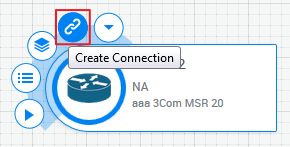
In the diagram, hover over a resource and from the context menu, select the Create Connection option.
-
Click a target resource to connect.
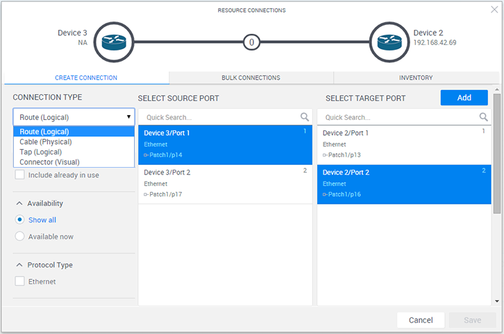
The Resource Connections dialog box is displayed, listing the ports in both the source and target resources that can be used to create the connectivity requirement.
-
From the Connection Type dropdown list, select the connection type.
Each connection type is represented by a color code (see View Physical Network Connectivity Requirements). For the different connection line types and icons used to indicate different connection variations, see Connections Legend.
Connection type Description Route (Logical) A route represents a logical connection between two endpoints that may or may not be connected directly and are represented on the diagram by lines. A route may be requested from a source resource that is connected indirectly to the target resource via an L1 switch or patch panel, it can also be used to represent a virtual network link between the two devices. Each of the inner connections between the source and target resource is a route segment. Route segments can be physical connections between two devices, or mapped connections within the switch or panel. Cable (Physical) Represents a request for a physical connection between two endpoints. The cable indicates a direct connection between two resources hence includes only one segment. This requires communicating the cable request to the system administrator who needs to physically connect the resources with a cable.
 More
More
The following workflow is provided to address situations where you need to make a physical connection between resources in the blueprint. A different workflow may be used to suit your organization's needs.
- Email the required cable connection to the system administrator. You can draw the connectivity lines between the resources in the blueprint and send them in a CSV file - see Exporting Diagrams.
- The system administrator connects the resources with a physical cable and notifies you that the connection is ready.
- Reserve the blueprint and create the missing connection using the Cable (Physical) connection type.
-
Connect the resources.
Once a connection is established, the broken connection line becomes a solid line.
Tap (Logical) Creates a type of route that represents a unidirectional connection from a tapped resource (source) to a monitoring device (target). The tap route is direction sensitive. Connector (Visual) This connection is visual only and can be created between any types of endpoints, connectable and non-connectable alike. This connection type does not have connected and disconnected states, just one default state. This type can be used for many different reasons. For example, to visualize some logical relation between endpoints in the diagram, or to pass information to the blueprint's orchestration or one of the resources regarding custom relations between resources.
This connection is also used for L2 and L3 connectivity (CloudShell determines this automatically based on the endpoints) - see Add Virtual Network Connectivity Requirements.
The available source and target port lists are updated according to the selected connection type.
-
Optionally, use the filters located in the left filter bar to find the ports to use. The following filters are available:
Filter category Options Resources - In this workspace: Selecting this option will display only ports that are already part of the workspace
- Include already in use: Selecting this option will include ports that are currently being used by other connections
Availability - Show all: Will display all ports either they are available or not
- Available Now: Will display ports that are currently available ( for blueprint editing only)
- For this sandbox: Will display ports that are available for the sandbox duration (for sandbox only)
Connectivity - Only disconnected: Will display ports that are not physically connected to any other device
- Only connected: Will display ports that are physically connected to another device
- Any status: Will display ports whether either they are physically connected or not
Domain (available for blueprint editing only) - Current domain: Deselecting this option will display ports from domains other than the current domain
It is also possible to add custom filters based on attribute values. For example, filtering by protocol type. To configure an attribute to be shown as a filter in the Resource Connections dialog box, enable the Displayed in Route Creation rule in the attribute in Resource Manager. The user should be able to filter ports based on the attributes values.
- To specify multiple routes between the two endpoints, see Add Multiple Physical Network Connectivity Requirements.
- From the Select Source Port pane, select the port of the source endpoint.
- From the Select Target Port pane, select the port of the target endpoint.
- Click the Add button to add the connectivity requirement. You can add more connectivity requirements between additional ports by repeating the same sequence.
-
Click Save to add the new route.
An indication message is displayed. For example:

When connecting the routes in a sandbox, CloudShell resolves the routes (establishes the required internal mappings in the L1 or Patch Panel resources along the route, or uses a Virtual Network if an App is included in the route).Tip: To check if the connectivity requirement you added can be solved, see Check Blueprint.
Related Topics